# A5 — Network Architecture & Switch Schedule
**Project:** Kingsford Hotel Bacolod BMS
**Date prepared:** 2026-04-27
**Source:** A-007 (isolated BMS LAN) · A4 panel schedule · BMS general spec on BMS-01
---
## Topology
Star-and-tree topology centered on the **BMS Server Room core switch**, with riser fiber to floor/zone edge switches, and Cat6 drops to BMS panels and BACnet/IP equipment.
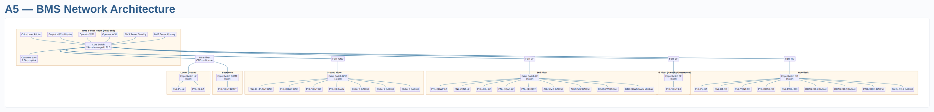
*Horizontal-orientation diagram — used in both the comprehensive proposal PDF and the internal PPTX. Auto-rendered from the mermaid below by `_playbook/tools/render-mermaid.py` per the visualize-network-architecture sub-routine. Source-of-truth is the mermaid; the PNG regenerates on every deliverables run.*
```mermaid
graph TD
subgraph "BMS Server Room (head-end)"
SVR1[BMS Server Primary]
SVR2[BMS Server Standby]
WS1[Operator WS1]
WS2[Operator WS2]
GFX[Graphics PC + Display]
PRT[Color Laser Printer]
CORE[Core Switch
24-port managed L2/L3]
UPLINK[Customer LAN
1 Gbps uplink]
SVR1 --- CORE
SVR2 --- CORE
WS1 --- CORE
WS2 --- CORE
GFX --- CORE
PRT --- CORE
CORE --- UPLINK
end
CORE === FBR_LZ[Riser fiber
OM3 multimode]
CORE === FBR_GND
CORE === FBR_2F
CORE === FBR_3F
CORE === FBR_RD
subgraph "Lower Ground"
SW_LZ[Edge Switch LZ
8-port]
PNL_PL_LZ[PNL-PL-LZ]
PNL_BL_LZ[PNL-BL-LZ]
SW_LZ --- PNL_PL_LZ
SW_LZ --- PNL_BL_LZ
end
FBR_LZ --- SW_LZ
subgraph "Ground Floor"
SW_GND[Edge Switch GND
16-port]
PNL_CH[PNL-CH-PLANT-GND]
PNL_BOH[PNL-CHWP-GND]
PNL_VGF[PNL-VENT-GF]
PNL_EM[PNL-EE-MAIN]
CH1[Chiller 1 BACnet]
CH2[Chiller 2 BACnet]
CH3[Chiller 3 BACnet]
SW_GND --- PNL_CH
SW_GND --- PNL_BOH
SW_GND --- PNL_VGF
SW_GND --- PNL_EM
SW_GND --- CH1
SW_GND --- CH2
SW_GND --- CH3
end
FBR_GND --- SW_GND
subgraph "2nd Floor"
SW_2F[Edge Switch 2F
16-port]
PNL_CHWP[PNL-CHWP-L2]
PNL_V2[PNL-VENT-L2]
PNL_AHU[PNL-AHU-L2]
PNL_DOAS_L2[PNL-DOAS-L2]
PNL_ED[PNL-EE-DIST]
AHU1[AHU-2M.1 BACnet]
AHU2[AHU-2M.2 BACnet]
DOAS2W[DOAS-2W BACnet]
BTU[BTU-CHWS-MAIN Modbus]
SW_2F --- PNL_CHWP
SW_2F --- PNL_V2
SW_2F --- PNL_AHU
SW_2F --- PNL_DOAS_L2
SW_2F --- PNL_ED
SW_2F --- AHU1
SW_2F --- AHU2
SW_2F --- DOAS2W
SW_2F --- BTU
end
FBR_2F --- SW_2F
subgraph "3rd Floor (Amenity/Guestroom)"
SW_3F[Edge Switch 3F
8-port]
PNL_V3[PNL-VENT-L3]
SW_3F --- PNL_V3
end
FBR_3F --- SW_3F
subgraph "Basement"
SW_B[Edge Switch BSMT
8-port]
PNL_VB[PNL-VENT-BSMT]
SW_B --- PNL_VB
end
FBR_LZ --- SW_B
subgraph "Roofdeck"
SW_RD[Edge Switch RD
16-port]
PNL_PL_HZ[PNL-PL-HZ]
PNL_CT[PNL-CT-RD]
PNL_VRD[PNL-VENT-RD]
PNL_DOAS_RD[PNL-DOAS-RD]
PNL_PAHU[PNL-PAHU-RD]
DOASR1[DOAS-RD.1 BACnet]
DOASR2[DOAS-RD.2 BACnet]
PAHU1[PAHU-RD.1 BACnet]
PAHU2[PAHU-RD.2 BACnet]
SW_RD --- PNL_PL_HZ
SW_RD --- PNL_CT
SW_RD --- PNL_VRD
SW_RD --- PNL_DOAS_RD
SW_RD --- PNL_PAHU
SW_RD --- DOASR1
SW_RD --- DOASR2
SW_RD --- PAHU1
SW_RD --- PAHU2
end
FBR_RD --- SW_RD
```
---
## Switch schedule
| Switch | Location | Ports | Type | Connects |
|--------|----------|------:|------|----------|
| **CORE** | BMS Server Room | 24 + 4 SFP | Managed L2/L3 (BACnet routing, VLAN, SNMP, NTP) | Servers ×2, WS ×2, GfxPC, Printer, riser fiber to 5 edge switches, customer-LAN uplink |
| **SW-LZ** | Lower Ground / Pump room | 8 + 2 SFP | Managed L2 | PNL-PL-LZ, PNL-BL-LZ, riser fiber to BSMT-SW |
| **SW-GND** | Ground / BOH | 16 + 2 SFP | Managed L2 | PNL-CH-PLANT-GND, PNL-CHWP-GND, PNL-VENT-GF, PNL-EE-MAIN, CH-1/2/3 |
| **SW-2F** | 2nd Floor IDF | 16 + 2 SFP | Managed L2 | PNL-CHWP-L2, PNL-VENT-L2, PNL-AHU-L2, PNL-DOAS-L2, PNL-EE-DIST, AHU-2M.1/2, DOAS-2W, BTU-CHWS-MAIN |
| **SW-3F** | 3rd Floor IDF | 8 + 2 SFP | Managed L2 | PNL-VENT-L3 |
| **SW-BSMT** | Basement | 8 + 2 SFP | Managed L2 | PNL-VENT-BSMT (riser via SW-LZ) |
| **SW-RD** | Roofdeck IDF | 16 + 2 SFP | Managed L2 | PNL-PL-HZ, PNL-CT-RD, PNL-VENT-RD, PNL-DOAS-RD, PNL-PAHU-RD, DOAS-RD.1/2, PAHU-RD.1/2 |
**Total switches:** 7 (1 core + 6 edge)
**Total active ports needed:** ~52 (network drops for panels + BACnet equipment)
---
## Cabling
| Item | Count / Length | Notes |
|------|----------------|-------|
| Riser fiber (OM3 multimode, 6-strand armored) | 6 risers × ~50 m avg = **300 m** | Server room → 6 edge IDFs |
| Fiber transceivers (1G SX or LX) | 14 (CORE × 5 risers + edge × 1 each) | Each end of each riser |
| Cat6 patch cables (1–3 m, factory-made) | ~80 (panel and core room patching) | Per A3 trunk estimate |
| Cat6 permanent links (at edge switches → BMS panels and BACnet equipment) | Already counted in A3 field cables | 27 BACnet/IP drops + 18 panel mgmt drops |
| 19" rack at BMS Server Room | 1 (per A6 HE-RACK-01) | Houses CORE switch + servers + UPS |
| Wall-mount enclosures at edge IDFs | 6 (1 per edge switch location) | 6U or 9U with patch panel + switch |
| UPS for CORE switch + servers | 1 (per A6 HE-UPS-01) | Already counted in head-end |
| Edge-switch UPS (small) | 6 × 500 VA | Optional — protects each edge switch from short outages |
---
## IP addressing plan (assumed)
- **BMS subnet:** 10.10.50.0/24 (isolated VLAN, 254 host addresses)
- **DHCP reservation pool:** .50–.99 for managed-static device assignments
- **Static blocks:**
- .10–.19: Servers and workstations
- .20–.29: Edge switches (network management)
- .50–.99: BMS controllers (per panel, allocated per A4 controller count)
- .100–.199: BACnet/IP equipment (chillers, AHUs, DOAS, PAHU, BTU meter)
- .200–.219: Power meter gateways
- **Default gateway:** .1 (CORE switch)
- **VLAN:** Single BMS VLAN (no segmentation in this scope; refine post-handover if required)
- **Customer-LAN uplink:** 1 Gbps to customer's IT closet (firewalled per Q-012); BMS WAN access TBD
---
## Network management & security
- All switches managed via SSH + SNMPv3 (BMS supplies credentials to customer at handover)
- BACnet/IP routing enabled at CORE for BBMD coordination if subnetting introduced
- Time sync via NTP from CORE (BMS server acts as time master, syncs to customer's NTP)
- No internet exposure for BMS LAN — all WAN access through customer firewall
- Q-012 will determine whether integration with PMS/FLS/CCTV/ACS adds IP allocation needs
---
## Open assumptions for A5
| ID | Assumption | Driver |
|----|-----------|--------|
| A-NET-001 | 1 Gbps fiber backbone, OM3 multimode, 6 risers | Sufficient for BMS data load (< 100 Mbps peak); fiber required for >90 m runs |
| A-NET-002 | 6 edge IDFs (one per floor/zone in scope) | Topology assumption — verify with Q-005 architectural |
| A-NET-003 | No VLAN segmentation; flat /24 BMS subnet | Simplest for handover; revisit if customer IT requires segregation |
| A-NET-004 | Edge switches managed L2 only (not L3 router) | CORE handles inter-VLAN routing if needed |
| A-NET-005 | UPS protection only for CORE + servers, not edge switches | Cost-down; optional 500 VA UPS per edge switch in OPT line item |
---
## Output for proposal
This A5 feeds:
- **Material BOQ** (Phase 6): switch count + types, fiber/Cat6 quantities, transceivers, racks/enclosures
- **Programming hours** (B1): controller IP plan, BACnet object naming, broadcast management
- **Installation manhours** (B4): network setup labor (drops × 0.5 hr in B4 already)
- **Network architecture submittal drawing** (Phase 1.3 deliverable)